
Debugging Circuit Blocks
So now I am testing out the functionality of circuit blocks where we package up a circuit into a re-useable part.
The Bus parts work OK, and the Register part worked out OK, but the Counter Part presented some issues.
The method that I am using to create tests is to first wire up the main part with Pins to provide inputs.
Then I save this as a circuit.
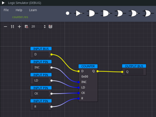
The next step is to save this circuit as a test circuit with a new name, delete the main part, and open the previous circuit as a block via the new File Menu option.
Then, wire this block up to the existing IO pins. Then we may check the Truth Table box and click on the counter icon to bring up the truth table.
We may test our circuit containing the block that is supposed to implement the counter to test it against the Truth Table.
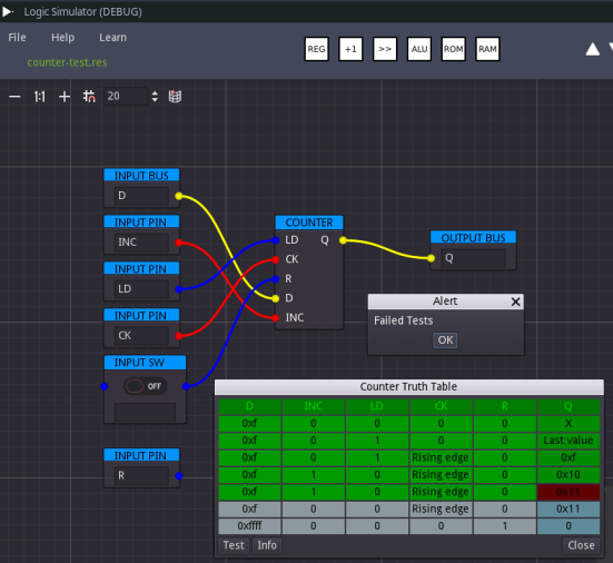
The first observation that may be made here is that the pins of the Counter block are not in the same order as the original part. This is a consequence of the Nodes of the pins being out of sync with the pin ordering in the scene tree.
This is a good thing since (to highlight a potential bug), later when users build a circuit, they could create the inputs in any order they like. The important thing is the connectivity.
So, I need to fix the code that generates the block part so that the ordering of the IO parts reflect their vertical positioning in the source circuit. I can do this by sorting them in a dictionary where their keys are based on the offset.y positions of them.
When actually running the Truth Table test, it fails at some point, and after investigation I don’t think that it has anything to do with the above issue. So that is what I need to debug next.
More Devlog entries
Most recent first
- 2021 10 02 New Release of Digital Logic Simulator
- 2021 08 28 Nested Sub Blocks
- 2021 08 27 Debugging with a log file
- 2021 08 26 Testing Circuit Blocks
- 2021 08 24 Bug Fixing with Blocks
- 2021 08 21 Circuit Blocks Update
- 2021 08 18 Circuit Blocks
- 2021 08 16 Highlighting of wires
- 2021 08 12 Adding Tutorial Content
- 2021 08 07 Numbers Scene
- 2021 08 06 Numbers Tabbed Scene
- 2021 08 04 Number Display Widget
- 2021 07 26 Logic Simulator Update
- 2021 07 24 - Launch of V1.0
- 2021 07 23 - Truth Tables
- 2021 07 22 Progress Update
- 2021 07 21 - Simple Computer Simulation
- 2021 07 16 - Community Forum
- 2021 07 15 - Community News
- 2021 07 11 - Save and Load ROM Data
- 2021 07 09 - Documentation About The Logic Simulator
- 2021 07 08 - Big Progress
- 2021 07 07 - RAM and ROM Testing Complete
- 2021 07 06 - Implementing Tests
- 2021 07 05 - Cool algorithm for binary text string
- 2021 07 04 - Debugging Complex Situations
- 2021 06 30 - End of June - Refactoring Continues
- 2021 06 29 Community
- 2021 06 28 Implementing More OOP
- 2021 06 27 Memory Parts
- 2021 06 26 Improving the Memory Manager
- 2021 06 25 Memory Data
- 2021 06 24 Memory Management
- 2021 06 23 First Devlog Entry