
Drawing Circuit Diagrams
We need some way to specify a circuit, and the most desirable way to do this is to have a CAD package. But we want to do it all in Godot so want some way to select from a palette of parts, and wire them up.
The way I chose to do this was to use the GraphEdit node. This allows for easy implementation of wiring up GraphNodes. The nodes have inputs on the left side and outputs on the right side called ports. These will be the pins of our component parts.
The wires are generated from Bézier curves, so the wires will not be made up of traditional horizontal and vertical segments. Also, the connections will only be from side to side, with no connects to the top or bottom of the parts.
So the circuit diagram will not look like a traditional CAD version, but I don’t care.
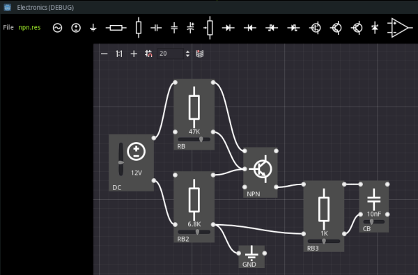
Some parts such as a vertically oriented resistor, will have left and right side pins effectively shorted, being the same connection electrically, but others will not such as a horizontally oriented diode.
We may create a theme for the project and apply a custom style to the GraphNode. For this, I simply created a StyleboxFlat to give a gray rectangle to replace the regular GraphNode appearance. Then use a TextureRect node to display a symbol for the particular part.
The part symbols were created in Inkscape and exported to an assets folder in the project. I decided to scale the part images by 50% to use as menu buttons to select parts. The Imagemagick utility via its convert function was used to do this.
convert -resize 50% *.png small/part.png
This creates images in bulk with names such as part-0.png, part-1.png, ...
Now, various part nodes were created in a parts scene and this was set to be Autoloaded since we will pick a part and duplicate it to add to our circuit. This parts scene needs to be hidden when we run the game.
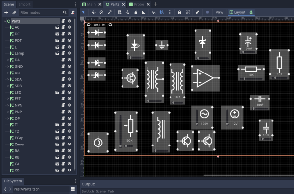
The part nodes have child nodes of Label, TextureRect, and maybe sliders. The sliders are used to set the value of a part.
The part values often increment over standard values for fixed-value parts such as 1K, 2.2K, 3.3K, .... Internally, we will store the values as floats.
The UI was constructed to have a top bar containing menu items, a side column to hold instruments for probing the circuit, and a graph area to display the circuit.
Scripts were added to handle the GraphEdit area for the connections, the general part script to be extended by the various parts, a main script, and a Data autoload for file-handling operations.
When a part in the menu is clicked, a new part is added in the center of the Graph ready to be dragged and dropped into place. Selected parts may be deleted by pressing the Del key.
A GraphData class resource file was created with various exported variables to be saved such as the nodes and connections. The nodes are parts with their own data to be saved. Then we use the ResourceSaver and ResourceLoader classes to easily and robustly save and load the circuit data in the user:// area.
So, the first stage was to get the UI working, be able to wire up circuits, and have save and load for the circuits working.
Next we need to extract a circuit from the Graph in the form of a network of nodes.
More Devlog entries
Most recent first