
Godot Level Editor
In this tutorial, I will explain how we may use the Tilemap to implement a Godot level editor which is then used to generate a scene.
Usually Tilemaps are used to directly draw the tiles of a 2D scene using a palette of tiles taken from a Sprite sheet for example. This is great for static content that fits into a grid, but how about dynamic content such as elevators, and moving platforms? We need a way to map these objects to the tiles.
What we can do is to create an Atlas (Sprite sheet) of icons for our types of content and paint these into Tilemaps. Each Tilemap may represent a Level in our Godot game editor. To process a Tilemap into a level we will run a script that scans the tiles and uses the coordinate value of the tile in the Atlas texture to match to a type of Node to add to the scene. The scene will be constructed from new nodes and then saved as a resource (scene) file.
Creating Icons
We will create Icons to use as tiles in Inkscape (vector graphics design software).
The icons will be laid out in a grid where the size of each icon matches that of a Tilemap grid cell size. For example 16x16 pixels square.
By zooming into the design grid we can get to the pixel level and snap to pixels easily. We can use the rectangle tool to draw filled rectangles with rounded corners and draw symbols on them with the Line tool. Ctrl+g groups objects, and Ctrl+d duplicates objects. By arranging the icons in a grid, we may then select them all and export as a single image.
Adding Tiles
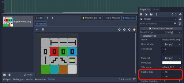
In the Tilemap inspector we may create a new Tileset. We will select our icons image and create a New Atlas. For this we will set the Subtile size to match the size of our icons. Then we select the area of the icons and this will create our Tileset which will appear in the Tilemap editor.
Tileset Editor
Tilemap Editor
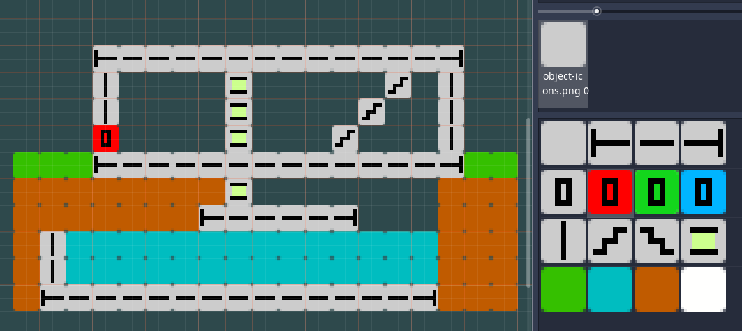
This method may also be useful for prototyping ideas for levels without needing to spend a lot of time creating graphics.
Mapping icons to objects
We may scan the cells of the Tilemap to determine the extents of the Tilemap coordinates with some code.
func scan_tiles():
	var tile_map: TileMap = get_tilemap()
	var cells = tile_map.get_used_cells()
	var parts = []
	if cells.size() == 0:
		return parts
	print("Scanning ", tile_map.name)
	# Get the bounding box
	var top_left = Vector2(INF, INF)
	var bottom_right = Vector2.ZERO
	for cell in cells:
		if cell.x < top_left.x:
			top_left.x = cell.x
		if cell.y < top_left.y:
			top_left.y = cell.y
		if cell.x > bottom_right.x:
			bottom_right.x = cell.x
		if cell.y > bottom_right.y:
			bottom_right.y = cell
This allows for the user placing tiles anywhere, even outside the visible area. Note the use of the INF (infinity) constant.
Now we are able to loop over the tiles by grid coordinates which ensures that we find the start or end of any object that is longer than one grid cell.
The most basic object will be a Sprite such as a tile of soil or water. And more complex objects will be elevators or conveyor belts for example.
We will gather the data for all the “parts” that we need to create for our scene. A “Part” will be defined by a class.
class Part:
	var id: int = -1
	var pos: Vector2
	var length: int = 1
This is added to an autoload script that also defines enum values for every kind of part and the order matches the order of the icons in our Tileset.
enum ITEMS {
	NONE,
	LEFT_END,
	PLAT,
	RIGHT_END,
	DOOR,
	R_DOOR,
	G_DOOR,
	B_DOOR,
	WALL,
	UP_STEPS,
	DOWN_STEPS,
	LIFT,
	GRASS,
	WATER,
	SOIL,
	SNOW
}
The code to scan the cells looks like this:
	var last_part = Parts.Part.new()
	# Scan cells and translate to parts
	for y in range(top_left.y, bottom_right.y + 1):
		for x in range(top_left.x, bottom_right.x + 1):
			# Match tile index value based off its autotile coordinate value
			if tile_map.get_cell(x, y) == TileMap.INVALID_CELL:
				last_part = Parts.Part.new()
				continue
			var id = get_cell_id(x, y)
last_part is a variable that stores a reference to an instance of the current part. You can see that we skip over empty cells, but where there is a tile, we derive an id value for it based on the grid coordinate of its parent tile in the Tileset.
This function is used to get the id value:
func get_cell_id(x, y):
	var v2 = $TileMap.get_cell_autotile_coord(x, y)
	return int(v2.x + 4 * v2.y)
This gives us an integer that equates with the enum value of the corresponding part type. So now we may apply the id to a match statement to decide what to do.
We will build an array of Parts.
To add a Part to the array, we will use this function:
func add_part(parts, id, x, y):
	var part = Parts.Part.new()
	part.id = id
	part.pos = Vector2(x, y)
	parts.append(part)
	return part
The parts array is passed by reference, so it will be updated within the function. The new part has its properties set accordingly and the new part instance value is returned since it needs to be remembered as the last_part. This is needed for when we scan for how many grid cells long a part should be and increment the part length value.
Code for something that may be long such as a platform:
	match id:
		Parts.ITEMS.PLAT:
			if last_part.id == id:
				last_part.length += 1
			else:
				last_part = add_part(parts, id, x, y)
Code for steps:
	match id:
		Parts.ITEMS.UP_STEPS, Parts.ITEMS.DOWN_STEPS:
			# Add if other part below it
			if get_cell_id(x, y + 1) > 0:
				last_part = add_part(parts, id, x, y)
				var x2 = x
				var y2 = y
				# Add up steps to the right
				while get_cell_id(x2 + 1, y2 - 1) == id:
					last_part.length += 1
					x2 += 1
					y2 -= 1
				# Add up steps to the left
				while get_cell_id(x2 - 1, y2 - 1) == id:
					last_part.length += 1
					x2 -= 1
					y2 -= 1
This finds the base of a flight of steps, adds the part at this position, then scans upwards to determine the length of the flight of steps. Until this point, the previous steps were ignored.
A similar method is used for vertical columns such as walls, elevators and doors.
	match id:
		Parts.ITEMS.DOOR, Parts.ITEMS.WALL:
			# Add if other part below it
			if get_cell_id(x, y + 1) != id:
				last_part = add_part(parts, id, x, y)
				var y2 = y - 1
				while get_cell_id(x, y2) == id:
					last_part.length += 1
					y2 -= 1
Miscellaneous filler tiles are just directly added.
	match id:
		_:
			last_part = add_part(parts, id, x, y)
Now we will have a list of parts to create nodes from.
Creating Nodes for Parts
We need to create scenes for each special part that we have in our game such as for an elevator. This would contain the sprites, collider shapes, logic that moves the elevator up and down between floors etc.
Also, there will be logic to construct the part to fit its length.
We will develop a scene generator script that starts with creating a new Node2D instance. Then we will add child nodes to this, make this node their owner, and then save this as a resource file.
Code for a part that grows vertically such as an elevator:
extends Node2D

export var height: int = 4

func _ready():
	if get_parent().name == "root":
		position = Vector2(100, 100)
	make_elevator(height)


func make_elevator(_height):
	_height *= Parts.SIZE
	$Top.position.y = Parts.SIZE -_height
	$Mid.scale.y = _height
	$Mid.position.y = Parts.SIZE -_height
	$Base.position.y = Parts.SIZE
The height value is set by the scene creation script and because it is an export var, the value is saved with the scene.
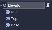
The object consists of three Sprites, and the position of these are set in the make_elevator function. Also, the 1-pixel height mid-section has its scale set to the height, and it appears behind the top and bottom sprites.
When the scene is loaded, the make_elevator function is called to set up the object. Also, if the scene is run by itself, the object is positioned such that it may be fully in view for test purposes.
If the scene is run directly, its parent node will be named “root”. That is how we may detect this situation.
Generating the scene
We start by instantiating a new Node2D and give it the name of the level.
Then we loop through the parts and either instantiate a Sprite or an instance of one of our part scenes (and set its height property). And we set the position of the object.
Code to instantiate a Sprite and getting the texture from a region of a Sprite sheet:
var sprite_sheet = preload("res://assets/spritesheet.png")

func get_sprite(region, flip = false):
	var sprite = Sprite.new()
	sprite.centered = false
	sprite.flip_h = flip
	sprite.texture = sprite_sheet
	sprite.region_enabled = true
	sprite.region_rect.position = region * Parts.SIZE
	sprite.region_rect.size = Vector2(Parts.SIZE, Parts.SIZE)
	return sprite
Code to instantiate objects:
var door_scene = preload("res://Door.tscn")

func generate_scene(level_name, parts):
	var node = Node2D.new()
	node.name = level_name
	for p in parts:
		var part: Parts.Part = p
		var child
		match part.id:
				Parts.ITEMS.NONE:
					continue
				Parts.ITEMS.DOOR:
					child = door_scene.instance()
					child.height = part.length
				Parts.ITEMS.ROCK:
					child = get_sprite(Vector2(6, 1))
		child.position = part.pos * Parts.SIZE
		node.add_child(child)
		child.owner = node
Finally, we save the scene to disk.
	var scene = PackedScene.new()
	var result = scene.pack(node)
	if result == OK:
		var error = ResourceSaver.save("res://levels/" + level_name + ".scn", scene)
		if error != OK:
			push_error("An error occurred")
Dealing with multiple levels
We can have several Tilemaps in our Level Editor scene. One way to control what Level is processed is to make the Tilemaps visible or not.
Then we run the scene and get the first visible Tilemap node for processing with this function:
func get_tilemap():
	var tile_map = TileMap.new()
	for child in get_children():
		if child is TileMap and child.visible:
			tile_map = child
	return tile_map
So hopefully this gives you some ideas for building a Godot Level Editor, thanks for reading.