
Digital Logic Simulator Manual
The window consists of a Top Bar showing File and Help menu links. Then there is a selection of Parts to click on to start using. Then, up/down icons allow for rotating around the various available Part selection menus.
If the box to the right is checked, then when clicking on a Part icon or actual Part that has a Truth Table, the Truth Table for that Part will be opened.
Truth Table
This specifies how a Part or Circuit must produce its Outputs in relation to the applied Inputs.
The given Pin names must match those found in the Circuit I/O Pins in order to test the circuit (when the Test button is pressed).
Any failure points during the test are highlighted in Red. Otherwise, it is colored Green to indicate the expected result.
File Menu
New
Clear the circuit (with a warning if it’s not saved).
Open
This is used to load previously saved circuits.
Displays a File selection Dialog which filters file names to only display .res files. You may also navigate to the folder that contains your files.
The loaded file name is displayed below the File menu link.
Save
This saves the current circuit or pops up the Save As dialog if it was not yet saved.
Save As
Displays a dialog to choose the location and file name of the circuit to be saved.
Learn
This tab, when clicked, opens a new tabbed scene.
Numbers
This scene contains tutorial text and a widget called a Number Spinner to learn about number systems.
Logic
This explains the basics of Boolean Algebra which is about operations on binary numbers.
Combinational Logic
About logic gates and combining them into common circuit arrangements.
Sequential Logic
This is about logic circuits that have memory of the state and may use a clock.
Building a circuit
Parts are added to the work area by clicking on them in the Part selection menu. Then the Part may be dragged around to reposition it.
Wire connections are added by clicking on a white (logic-level) pin or yellow (Bus) and dragging out the wire to a destination pin. If the connection is allowed, then the wire should snap into place to complete the connection.
Some Parts have editable names such as I/O Pins. Other Parts have selectable numbers of Bits where a Button is clicked to set the value. Then, the Button may be removed. Other Parts have a Button to rotate around the display format of the Bus data value.
To remove a Part or a group of Parts: select them and press the Delete key.
To easily re-save a circuit; press Ctrl+s
Signal Flow
The flow of Inputs to Outputs is generally from the Left side towards the Right side. But, the Switch Parts allow for sending both ways. Also, the Loop Bus Part allows for looping back of a Bus with the idea to make it easier to wire up 7-segment displays in a natural order.
7-segment display
This has a Button to set the preferred color of the segments.
The dot is displayed when the number value exceeds 9.
The Bus output of the 7-segment display has its value divided by 10 or 16 depending on the set mode for it. This allows for chaining of the displays to display multi-digit numbers in Hex or Decimal.
Memory
The ROM may store a program that gets saved with the circuit.
The RAM is a volatile storage area that initially contains zeros.
A Memory Manager Tool is attached to the Memory Parts. This allows for configuration of the Memory size and 8-bit or 16-bit data words. Also, you are able to Erase the Memory and Edit individual Words in Hex or Binary format.
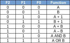
ALU
The Arithmetic and Logic Unit (ALU) part has A and B inputs. The function performed on them to produce the output is set with the F0, F1, and F2 inputs as follows:
The bus width may be set to 4/8/16 bits by clicking a button.
Y is the output depending on the selected function.
The various output flags are as follows:
Cout is high if there is an unsigned overflow.
Zero is high if the output at Y is zero.
Over is high if the sign bit changed indicating a signed overflow.
Sign is set if the sign bit was set.
Challenges
Challenges are in the form of trying to construct a circuit from primitive parts to pass a Truth Table Test. Starting with simple up to advanced challenges.
For example:
- create a Flip-flop circuit
- create a full adder circuit
- create a computer circuit
- run code on the computer